RODI Systems Corp. Water and Wastewater Treatment Systems, Controls, Instrumentation
  • Home
  • Products
    • RODI Products
    • Ceramic Membrane
    • Chemical Feed Systems
    • Controllers & Instruments
    • Custom Controllers
    • Desalination Systems
    • High Purity Systems
    • Silt Density Monitors
    • Wastewater Treatment Systems
    • Water Purification Systems
    • Water Treatment for Hydrogen Production
  • About Us
    • About RODI
    • RODI Projects
    • RODI Customers
    • Industries
    • Technologies
  • Get Support
    • Technical Support
    • How To Buy Standard Products
  • Contact RODI
  • Resources
    • How Does Reverse Osmosis Work?
    • What is Desalination?
  • Blog

AquaLynx™ 250 ENC V2
Reverse Osmosis Monitoring and Control System

BACKGROUND
The RODI Systems AquaLynx™ 250 ENC V2 is a compact data acquisition, monitoring, and control system designed specifically for commercial and light industrial RO applications. Utilizing the latest microprocessor technology, over four thousand variants of this controller have been deployed since 2001. The AquaLynx™ 250 ENC V2 is a "drop in" replacement for the MC10 RO controller originally used by US Filter, Siemens, and Evoqua.
HARDWARE: INPUTS & OUTPUTS
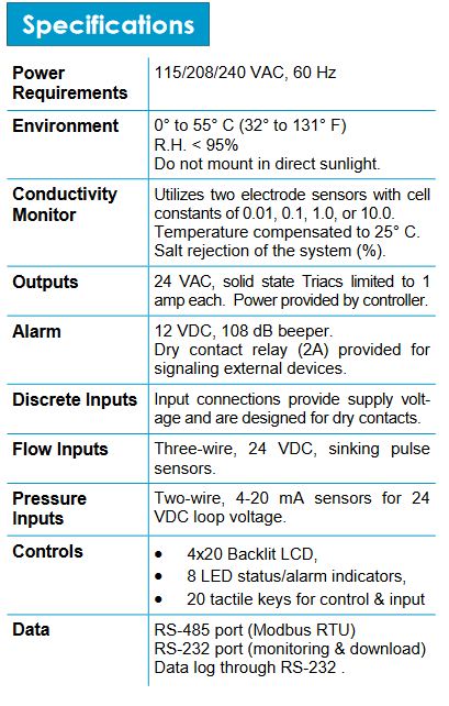
The AquaLynx™ 250 ENC V2 RO Controller is equipped with the following inputs. Input connections are made via spring terminals.
  • Two Conductivity Sensors: Two inputs are provided for two-electrode conductivity sensors on the RO feed and product. Sensors with cell constants of 0.01, 0.1, 1.0, or 10.0 may be used.  These cell constants provide a detection range of 1 uS/cm to 100,000 uS/cm. Only sensors with a 1000 ohm RTD will work with this controller.
  • Four Pressure Sensors:  4-20 mA inputs for pressure sensors monitoring feed pressure, interstage pressure, reject pressure, and permeate pressure. Pressure sensor inputs may be disabled for systems without these sensors.
  • Three Flow Sensors: Inputs for two sinking pulse flow sensors on any combination of feed, reject, or permeate along with one sinking pulse sensor for reject recycle. Flow sensor inputs may be disabled for systems without these sensors.
  • Two Pressure Switches: Dry contact inputs for low pump suction and high pump discharge.
  • Two Tank Level Switches: Dry contact inputs for high land low tank level switches.
  • Pretreatment Interlock: Dry contact input that signals the system to shut down when a pretreatment device is not functioning or is regenerating.
  • Pretreatment Failure: Dry contact input that signals the failure of the pretreatment system .
The AquaLynx™ 250 ENC V2 is equipped with the following outputs. The 24 VAC outputs are in the form of solid state triac outputs. Output connections are made via screw terminals.
  • Inlet Solenoid: Energizes 15 seconds before the high pressure pump turns on, and de-energizes 15 seconds after the pump turns off.
  • Auto Flush Valve: This output energizes during the flush cycle, thus opening the valve and allowing flow to bypass the reject control valve.
  • Chemical Injection Pump: Energizes before the high pressure pump starts and de-energizes before the pump shuts down.
  • High Pressure Pump: Powers the coil of the high pressure pump motor starter. This output is energized depending on other operating parameters.
  • Permeate Diversion Valve: Energized when the percent salt rejection of the system is below the setpoint. This output is also energized during a flush.
  • Alarm: Includes a 108 dB alarm horn mounted inside the AL250-V2 enclosure along with a dry contact relay for interfacing with other devices.
All 24 VAC outputs are protected by positive temperature coefficient resistors (polyfuses).
Request a Quote Now
Download full spec sheet
reverse osmosis monitoring and control
FEATURES
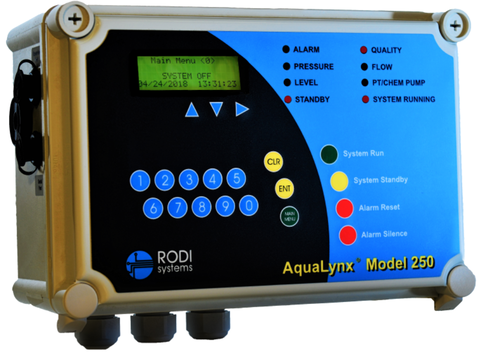
The AquaLynx™ 250 ENC V2 is equipped with eight labeled LED indicators and an intuitive LCD display. This backlit 4 line x 20 character LCD is used to display operating data such as:
  • Feed and Permeate Conductivity
  • Feed Temperature
  • Salt Rejection Percentage
  • Feed, Reject, and Permeate Flows (including Recovery)
  • Feed Interstage, Reject and Permeate Pressures
  • Total Run Time
The display is also used along with the keypad for password protection and settings management.

Eight high-intensity LED indicators are located on the front of the AquaLynx™ 250 ENC V2. These LED indicators provide an easy to see system status. These indicators provide vital information without having to navigate the LCD screen. Indicator functions are described below.
  • Alarm: A general alarm indicator for all alarm conditions. Major alarms are also indicated by additional specific indicators (described below). Infrequent alarm conditions, such as high feed temperature, are indicated by the “ALARM” indicator. All alarms may be viewed on the LCD.
  • Pressure: Indicates high membrane feed pressure and low suction pressure.
  • Level: Blinks when the tank is full. Steady illumination indicates that the tank is being drawn down while in standby.
  • Standby: Indicates the system is in standby mode. Blinking indicates that the system is flushing.
  • Quality: Indicates permeate conductivity is high, salt rejection is low, or permeate diversion is taking place.
  • Flow: High recovery or low reject flow.
  • PT/Chem Pump: Indicates when the system is experiencing failure of the chemical injection or pretreatment system. The system will shut down after the PT/chem pump failure time delay expires. Also indicates when the system is shut down due to external pretreatment equipment.
  • System Running: Indicates that the system is running in either tank feed or direct feed mode.
DIMENSIONS
dimensions of the AL 250 RO ENC V2
SETTINGS
The AquaLynx™ 250 ENC V2 may be programmed with the following settings. All settings are easily changed from the keypad and are password protected.
  • Alarm Setpoints, Deadbands, and Time Delays
  • Permeate Diversion Setpoint, Deadband, and Time Delay
  • Calibration Settings for Conductivity, Temperature, and Pressure
  • Conductivity Range
  • K Factors for Flow Sensors
  • Enable/Disable for Tank Level Sensors, Pressure Sensors, and Flow Sensors
  • Flow and Pressure Sensor Configuration
  • Logic Settings Including:
    • Low Pressure Restart Delay
    • Tank or Direct Feed Selection
    • Tank Level Start Delay
    • Flush Interval
    • Flush Duration
The AquaLynx™ 250 ENC V2 logs all alarm events along with time-stamped conductivity, temperature, pressure, and flow data.

AquaLynx™ is a trademark of RODI Systems Corp.
Picture

Contact Us

(505) 334-5865
RODI Systems Corporation
936 Highway 516, Aztec, NM 87410
[email protected]
Social Media

Search this site

Read our Terms and Conditions.
  • Home
  • Products
    • RODI Products
    • Ceramic Membrane
    • Chemical Feed Systems
    • Controllers & Instruments
    • Custom Controllers
    • Desalination Systems
    • High Purity Systems
    • Silt Density Monitors
    • Wastewater Treatment Systems
    • Water Purification Systems
    • Water Treatment for Hydrogen Production
  • About Us
    • About RODI
    • RODI Projects
    • RODI Customers
    • Industries
    • Technologies
  • Get Support
    • Technical Support
    • How To Buy Standard Products
  • Contact RODI
  • Resources
    • How Does Reverse Osmosis Work?
    • What is Desalination?
  • Blog