|
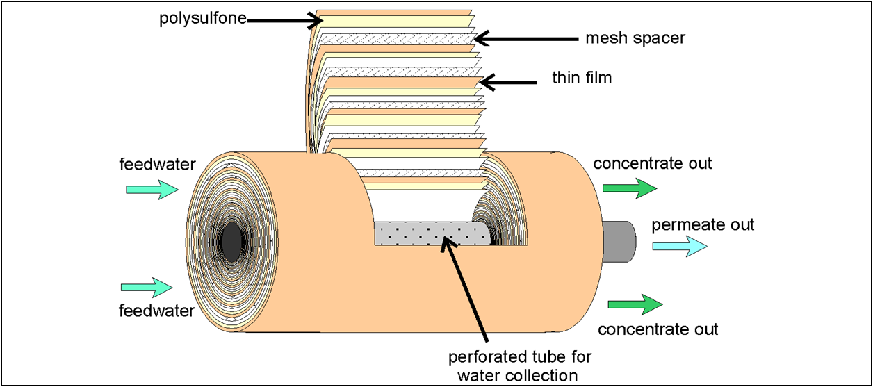
In order to operate and maintain RO systems properly, it is important for technicians to understand the construction of the RO membrane elements. RO membranes use a cross-flow filtration technique, where only a portion of the water passes through the membrane. The remaining flow passes across the membrane and through the treatment system as waste (also called concentrate, reject or brine). This waste- or concentrate-flow is necessary to keep fouling materials from building up too rapidly on the surface of the membrane. The cross-flow membrane treatment systems have one feed stream entering the system, one concentrate stream and one permeate stream (purified water) leaving the system. Any membrane treatment technique is limited by the amount of water that can be forced through a given area of membrane in a given amount of time. This flow, referred to as the membrane flux rate, is often reported in gallons per square foot per day (GFD). For a treatment system to be able to treat more water, more membrane must be present. The membrane is used under pressure, so it must be enclosed inside a pressure vessel (PV). For the sake of economy, the volume of these PVs must be as low as possible. The goal is to put as much membrane in as small a volume as possible while still making provisions for feeding water to the membrane surface and removing concentrate and permeate. While RO membranes are available in a number of configurations, one of the most common is the spiral wound. In this design, two flat sheets of membrane are glued together back-to-back to form an envelope. Inside the envelope is a porous sheet of material called a permeate carrier. The envelope is glued together on three sides. The fourth side of the envelope is attached to a perforated permeate tube. The only way water (permeate) can exit the envelope is through this tube. During operation the feedwater (under pressure) flows across the membrane surface on both sides of the envelope. Water, which permeates through the membrane, flows along the permeate carrier toward the open end of the envelope and exits through the permeate tube. In large industrial systems several envelopes are attached to the perforated permeate tube in such a way that the permeate exiting the envelopes has to enter the same permeate tube. The envelopes are then wrapped, or wound, around the permeate tube to form a cylindrical membrane element. Before the envelopes are wrapped, a mesh feed spacer is placed between the envelopes. The feed spacer is necessary to provide a space between membrane envelopes after the envelopes are wrapped into the spiral wound configuration. This space, called the feed channel, allows the feedwater to flow evenly through the element from one end to the other.
Elements are placed end-to-end in a cylindrical pressure vessel (PV). The permeate tubes of each element are connected to form a permeate channel which allows the permeate from the collective elements to exit one end of the PV. Feedwater enters one end of the PV, and concentrate exits the other. A typical industrial element is 8” in diameter by 40” in length. PVs may hold one to eight elements, with six being the average. RO systems may have from one to hundreds of PVs.
7 Comments
|
Categories
All
Archives
October 2022
|
Contact Us(505) 334-5865
Social Media
|
|


 RSS Feed